
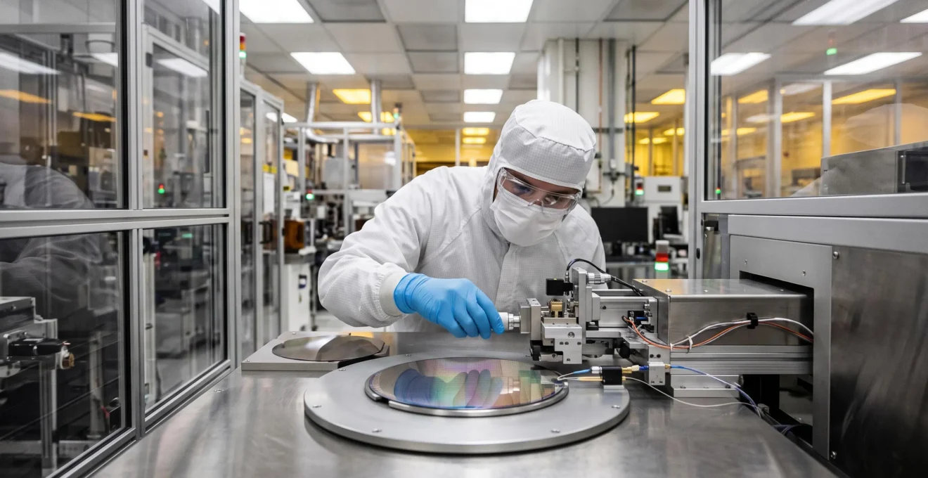
A pre-aligner ensures exact Z-axis positioning and theta orientation by combining non-contact sensors, a closed-loop correction algorithm and precision actuation on both a vertical stage and a rotary chuck. Height is measured by a laser or capacitive sensor, rotation is referenced through edge detection or notch finding, and both values are driven toward target coordinates until the residual error falls within specified tolerances. Published work on wafer pre-alignment reports simulated position accuracy of ±2 µm and angular accuracy of 0.01°, which illustrates the order of magnitude engineers can expect from a well-integrated system compared with manual calibration.
Direct answer: A pre-aligner measures Z height and theta angle with dedicated sensors, computes the deviation from a target, and corrects the position through a vertical actuator and a rotary stage until the error is within tolerance, typically a few microns on Z and a fraction of a degree on theta.
What Is a Pre-Aligner and Why Z and Theta Matter
A pre-aligner is a dedicated handling module placed upstream of a process tool or robot end-effector. Its role is to receive a part, typically a semiconductor wafer or a disc-shaped substrate, and present it to the downstream station with a known, repeatable position and orientation. Without that intermediate step, a robot inherits every pick-up variation accumulated along the handling chain, which quickly becomes incompatible with micron-level process windows.
Two degrees of freedom are especially critical. The Z axis controls the vertical position of the part, which drives the focal distance for inspection, the clearance for exchange with another chuck or the stand-off for a dispensing tool. The theta axis controls the rotational orientation around the vertical, which determines where the notch, flat or any angular feature of the part faces after transfer. A documentary resource on precision handling architectures is available on eumetrys-robotics.com, which centralises technical information on robotic alignment solutions.
Think of the pre-aligner as the equivalent of aligning a key before inserting it into a lock: the lock mechanism itself cannot compensate for a key presented upside down or at the wrong depth. In production, a drift of a few hundred microns on Z or a few tenths of a degree on theta is often enough to cause broken contact, missed vision targets or scratched surfaces downstream.
Why Z and theta drive downstream quality
- Z sets the vertical reference for focus, clearance and transfer height.
- Theta sets the angular reference for notches, flats and patterned features.
- Both are measured and corrected before the part reaches the process tool.
- Residual error on either axis propagates directly into downstream yield.
How a Pre-Aligner Ensures Exact Z-Axis Positioning
Z-axis control starts with a non-contact measurement of the part surface relative to a mechanical reference, usually the chuck plane. Laser triangulation sensors, confocal sensors or capacitive probes are commonly used because they measure height without touching the part, which protects fragile substrates and avoids particle generation in cleanroom environments. The measurement is sampled continuously or at well-defined angular positions while the chuck rotates.
The pre-aligner then runs a closed-loop correction: the controller compares the measured height to the target Z coordinate, computes the deviation, and commands a vertical actuator to compensate. The loop iterates until the residual error falls below a defined threshold. The achievable precision depends less on the sensor alone than on the combined chain of sensor resolution, actuator repeatability, mechanical rigidity and chuck flatness.
Orders of magnitude observed on dedicated precision stages illustrate what the Z axis of a well-designed system can deliver. A manufacturer specification sheet for a piezo wafer positioning stage from Physik Instrumente states a Z axis offering 10 nm bidirectional repeatability and sub-5 nm position stability, over a coarse travel of 4 mm combined with a 50 µm fine range. These values describe a positioning stage rather than a complete pre-aligner, but they bound what the actuation layer alone can contribute.
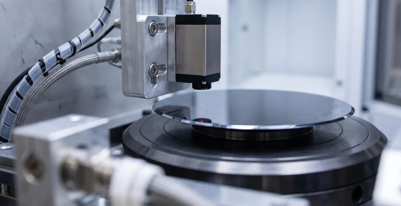
A typical Z correction sequence runs in four steps. First, the part is placed on the chuck and clamped by vacuum. Second, the height sensor acquires one or several measurements while the chuck is held static or rotated slowly. Third, the controller computes the delta between measured and target heights. Fourth, the Z actuator moves to compensate, and a verification measurement confirms that the residual error is within tolerance before the part is released to the next station.
How Theta Orientation Is Measured and Corrected
Theta control uses the geometry of the part itself as a reference. On a wafer, the orientation feature is either a notch cut into the edge or an orientation flat. An edge sensor, typically a line-scan camera, a through-beam optical sensor or a laser micrometer, monitors the part edge while the chuck rotates a full turn. The controller logs the edge position as a function of angle and extracts both the geometric centre and the angular location of the notch or flat.
Once the notch is located, the pre-aligner commands the rotary stage to bring it to the target angle defined by the recipe. The achievable accuracy depends on the rotary stage resolution, bidirectional repeatability and backlash behaviour, as well as on the sampling density of the edge measurement. A granted USPTO patent on aligner correction methods formalises this principle, describing a wafer aligner that detects the notch or orientation flat formed in the outer peripheral edge and positions the wafer at a predetermined rotation position.
Published simulations give concrete figures. A peer-reviewed wafer pre-alignment study hosted on PMC reports a simulated absolute position accuracy of ±2 µm and absolute direction accuracy of 0.01°, with sensor detection accuracies of ±3 arcseconds for angle and ±1 µm for distance, and a total calculation time below 3.3 s. These values describe a simulated algorithm, not a universal benchmark, but they anchor the order of magnitude engineers can discuss with suppliers.
In practice, a notched wafer is placed on the vacuum chuck, which rotates one full turn while the edge sensor records the profile. The controller identifies the notch as a localised deviation, computes the angular offset between its current position and the target angle, then commands the rotary stage to rotate by that offset. A verification turn, or a differential measurement, confirms that the final angular error is within tolerance before the part is handed off.
Which Parameters Should Engineers Monitor for Reliable Alignment?
Reliable alignment is not only a matter of initial accuracy. The parameters that matter in production describe how the system behaves across many cycles, many parts and extended operating time. Repeatability, measured as the standard deviation of position or angle over successive cycles with the same part, is often more constraining than absolute accuracy for process stability.
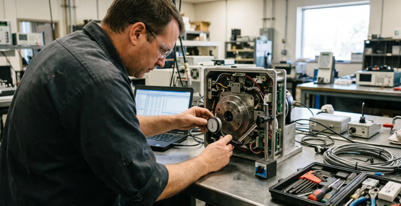
Common sources of misalignment are well identified. Mechanical play in the rotary stage introduces backlash that must be compensated by always approaching the target from the same direction. Sensor drift, caused by temperature changes or contamination, biases the measurement and must be bounded by periodic recalibration. Part-to-part variation, such as wafer thickness tolerance or edge geometry, propagates into the measurement and must be handled by the algorithm rather than assumed negligible.
- Define tolerances
Set explicit numerical targets for Z accuracy, theta accuracy, repeatability and cycle time, derived from the downstream process window.
- Characterise sensors
Verify sensor resolution and noise on a reference part before integration, and record the baseline for future drift comparisons.
- Measure repeatability
Run a statistically meaningful number of cycles with the same part and compute standard deviations on Z and theta separately.
- Test part variability
Repeat measurements with several representative parts to isolate the contribution of part-to-part variation.
- Plan recalibration
Define the frequency and procedure for sensor and stage recalibration, and tie it to a preventive maintenance plan.
Watch for silent drift: A pre-aligner can keep producing within-spec cycles while slowly drifting toward the tolerance limit. Trending repeatability and residual error over time, rather than checking only acceptance pass/fail, is often the earliest signal of a mechanical or sensor issue.
Choosing and Integrating a Pre-Aligner Solution
Selecting a pre-aligner starts with a clear specification: the type and size of parts to handle, the required Z and theta tolerances, the throughput in cycles per hour, and the mechanical and electrical interfaces to the existing cell. These four criteria usually eliminate most candidates before any commercial discussion begins. A pre-aligner optimised for 300 mm wafers in a semiconductor cluster tool has little in common with one designed for smaller substrates in an inspection cell.
Pre-aligner versus manual calibration
- Repeatable Z and theta correction across every cycle, independent of operator skill.
- Measured residual error available for traceability and process monitoring.
- Compatible with full automation and higher throughputs.
- Reduces risk of part damage from repeated manual handling.
- Accuracy depends on operator attention and available metrology tools.
- No in-line verification of residual error on each part.
- Scales poorly with volume and shift changes.
- Difficult to document for quality audits.
Integration into an existing robotic cell raises three practical questions. First, mechanical: is there room for the pre-aligner within the robot envelope, and is the chuck height compatible with the end-effector trajectory. Second, electrical and communication: does the controller support the required protocol, and can alignment data be logged by the cell supervisor. Third, timing: does the pre-aligner cycle fit within the overall takt time, including the exchange with the robot.
For teams that need to confront these criteria with a reference architecture, structured documentation from a specialist in precision robotic alignment can accelerate the specification phase. Comparing published tolerance ranges, actuator technologies and sensor configurations against the actual downstream process window usually clarifies whether a pre-aligner is justified or whether a simpler fixture would suffice.
What accuracy can I realistically expect from a pre-aligner on Z and theta?
Published simulation results on wafer pre-alignment report ±2 µm on position and 0.01° on direction, with angle detection at ±3 arcseconds and distance detection at ±1 µm. Dedicated precision stages reach 10 nm Z repeatability and 0.5 µrad theta repeatability in manufacturer datasheets. Real-world performance depends on the complete chain of sensor, actuator, chuck and part, so these figures should be used as orders of magnitude, not guarantees.
How is the theta orientation actually detected?
An edge sensor records the part edge profile while the chuck rotates a full turn. The controller identifies the notch or orientation flat as a geometric singularity in the profile and computes the angular offset between its measured position and the target angle. The rotary stage then rotates by that offset.
Does a pre-aligner replace a vision system downstream?
No. A pre-aligner provides a known, repeatable mechanical reference before the part enters the process tool. A downstream vision system still performs fine alignment at the micron or sub-micron level when the process requires it. The pre-aligner reduces the search range the vision system must handle, which improves speed and robustness.
What are the most common causes of alignment drift in production?
Mechanical backlash in the rotary stage, thermal drift of the sensors, contamination on the chuck surface and part-to-part geometric variation are the recurring culprits. Each has a dedicated mitigation: unidirectional approach for backlash, periodic recalibration for drift, cleaning procedures for contamination, and algorithmic handling for part variability.
Choosing a pre-aligner comes down to matching measurable tolerances to a measurable process need. When the downstream window on Z is a few microns and on theta a fraction of a degree, a dedicated pre-aligner usually pays back quickly through fewer rejects and faster commissioning. When the window is loose and volumes are low, a well-designed fixture may still be the pragmatic choice. The deciding factor is rarely the datasheet alone but the combination of required tolerance, throughput, traceability and the cost of a single misaligned part.